
Actual vs effective focal spot
- The actual focal spot is the physical area of electron impact on the anode target.
- The effective focal spot is the apparent size of this region as projected towards the image receptor.
A smaller focal spot produces sharper images but limits tube loading capacity; a larger focal spot tolerates higher currents but increases unsharpness.
The line focus principle
We’ve discussed this previously, but to revise:
The line focus principle allows for a small effective focal spot (improved resolution) while maintaining a large actual focal area (improved heat dissipation).
- Achieved by angling the anode target (typically 6–20°) relative to the electron beam.
- The projected (effective) focal spot is smaller than the actual impact area:
Effective focal length = Actual focal length ×sin(θ)
where θ = anode angle.
Why don’t we always use the smallest focal spot possible to get the best spatial resolution?
- Smaller anode angles create a smaller X-ray field which might not be big enough to cover large anatomy or a large detector.
- The smaller the anode angle the more the heel effect.
- Long exposure times aren’t tolerated well by anodes with a small anode angle.
Geometric unsharpness (Blur/ Penumbra)
Image sharpness is limited by geometric unsharpness (Ug). Geometric unsharpness is blurring at the edges of structures caused by the size of the focal spot. In an ideal world the focal spot would be infinitely small and no blurring would occur. Geometric unsharpness is defined by:
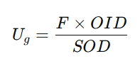
where:
- F = focal spot size
- OID = object–image distance
- SOD = source–object distance
To reduce geometric unsharpness:
- Use a smaller focal spot.
- Reduce OID (bring patient closer to detector).
- Increase SOD (increase source to patient distance).
Beam divergence and magnification
The X-ray beam diverges from the focal spot, forming a cone-shaped geometry.
This causes magnification and shape distortion of the image depending on object and detector positioning.
Magnification Factor (MF):
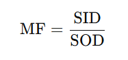
where SID = source–image (detector) distance, SOD = source-object (patient) distance.
Reducing magnification:
- Use a long SID.
- Keep the patient close to the detector.
Clinical examples:
- Chest radiography uses a long SID (~180 cm) to reduce cardiac magnification.
- In fluoroscopy, shorter SIDs cause greater magnification and geometric distortion.
Focal spot blooming
At high mA or prolonged exposures increased electron repulsion (space charge effect) can enlarge the electron beam, causing focal spot bloom and loss of sharpness.
Modern tubes use electrostatic focusing and precise filament control to minimise these effects.
Key takeaways and exam tips:
- The focal spot is where X-rays are generated on the anode.
- Effective focal spot = actual × sin(anode angle).
- Smaller anode angle → smaller effective spot → sharper image.
- Geometric unsharpness (Ug) ∝ F × OID / SOD.
- Use long SID and small OID to minimise magnification and blur.
- Focal spot bloom occurs at high mA due to electron repulsion.
- Common exam questions: “What determines spatial resolution in radiography?” → remember to include focal spot size (we’ll discuss other factors later, one thing at a time, let’s not get ahead of ourselves). “Which factors reduce geometric unsharpness”, “Explain the line focus principle and how effective focal spot is calculated” → include trade-off between spatial resolution and tube durability.
Up next:
Next, we’ll discuss Beam collimation and filtration. Two steps that improve image quality and reduce patient dose. A win-win situation!